
- Bearing Distributors Inc
- Spherical Roller Bearings SKF bearing Deep Groove Ball Bearing

Home> Technical Articles> Roller bearing bushing reference
- Address1589 Tampines Industrial Distributor Avenue 5 Singapore 528759
- Factory Address1589 Tampines Industrial Distributor Avenue 5 Singapore 528759
- Worktime9.00--18.00
- Phone(Working Time)0065-31591338
- Phone(Nonworking Time)0065-31591338
- Fax0065-31591338
Roller bearing bushing reference
NOVEMBER 02, 2022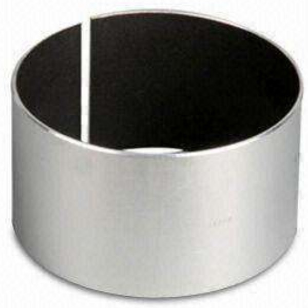
The transformation of the sliding bearing of a conventional ball mill into a rolling bearing is one of the important measures for energy saving in the industry. In this process, a rolling bearing bushing is applied. The outer surface of the tapered bushing is tapered, and the inner bore of the rolling bearing is tapered. The rolling bearing is gradually pushed from the small end of the tapered bushing to the big end to reach the preset position, and then the outer ring is fixed to the small end of the bushing, and the stop provided on the outer ring is to withstand the rolling bearing The side of the inner sleeve, the other side of the rolling bearing inner sleeve is not limited. In actual use, there are two shortcomings. 1 If the matching journal wear is serious, after the tapered bushing is mounted on the journal, the rolling bearing must advance to the large end of the bushing. The more serious the journal wear, the more the roller bearing pushes toward the big end of the bushing. Ensure an effective fit between the rolling bearing and the tapered bushing. When the rolling bearing has a large amount of propulsion, the preset length of the outer ring is limited, and the side of the inner sleeve of the rolling bearing is not accessible, which may cause the two sides of the inner sleeve of the rolling bearing to be incapable of being limited. Conversely, if the journal wear used is very small, the rolling bearing will advance to the large end of the bushing. If the retaining ring of the outer retaining ring is reserved too long, it will retreat to the small end of the bushing, and the bearing The inside of the seat seals the inside of the cover. 2 When the ball mill produces a large axial force during operation, the direction of the force is bidirectional. If the axial force is directed from the small end of the tapered bushing to the large end, the axial force can be withstood due to the contact of the outer ring with the small end of the rolling bearing inner sleeve; if the axial force is tapered The large end of the bushing is pointed at the small end. Due to the infinite position of the rolling bearing inner sleeve at the large end of the tapered bushing, the shaft and the tapered bushing are gradually pushed toward the small end, because the bearing shell ends are sealed by the sealing cover on both sides of the bearing seat. Under the action of this force, the large end of the tapered bushing continuously enters the inner sleeve of the bearing, which increases the interference of the inner sleeve and the bushing of the rolling bearing, such as long-term propulsion. The interference is too large, and the inside of the rolling bearing The sleeve is broken, causing the rolling bearing to fail. When the ball bearing sliding bush is transformed into a rolling bearing, some running time is not normal, and this happens, causing serious consequences.
1 new bearing bushing technical solution
The new bushing is designed to limit the two-way rolling bearing inner sleeve and to adjust the limit distance [2]. The roller bearing bushings include a multi-lobed tapered bushing, a small-end T-flange, a large-end T-flange, and a limit bolt.
The inside of the multi-lobed tapered bushing is cylindrical and fits with the journal; the outer part is conical and cooperates with the inner hole of the rolling bearing; the tapered bushing is usually designed as two flaps, and can also be designed as 3-6 petals, and some flaps A through hole is provided at the joint, and some of the petals are provided with an internal threaded hole at the joint, and the bolt is screwed through the through hole to screw the other threaded internal thread hole, so that the two and two are connected, and the flap of the tapered bushing is The petals are fixedly connected; a plurality of internally threaded holes are provided in the large end face and the small end face to fix the T-shaped flange, and the number and position of the internally threaded holes are the same as those provided on the T-shaped flange. The large end of the tapered bushing has exactly the same shape as the small end. Due to the taper, the diameter of the big head is larger than the diameter of the small head. The calculation method of the increase is:
D = ILtanq, where (i) is the length of the tapered bushing and 9 is the taper angle of the inner bore of the rolling bearing.
The small end T-flange is usually set to two lobes and can also be composed of 3 to 6 lobes. The inner part of each of the petals is a cylindrical surface and cooperates with the journal; some of the petals are provided with through holes at the joints, and some of the petals are provided with internal threaded holes at the joints, and the bolts pass through the through holes to screw the internal threaded holes of the other petals The valve and the flap are connected by this method; on the large disc, there are two rows of circularly arranged holes, and the inner side is a through hole, and the bolt is inserted through the through hole and screwed into the large end surface of the tapered bushing. Inside the internally threaded hole, the T-shaped flange can be fixed, and the outer side is an internally threaded hole for fixing and adjusting the limit bolt. The through hole and the internally threaded hole are at least two or more.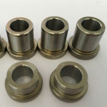
The large-end T-flange and the small-end T-flange are identical in shape and have different sizes. The diameter of the large disk here is larger than the diameter of the large disk at the small end, and the amount of increase is calculated as described above. On the large plate here, the diameter of the circle of the center line of the two rows of holes is also adjusted accordingly, but the number and diameter of the through holes and the internally threaded holes are unchanged. In application, the two lobes of the large-end T-shaped flange are placed on the journal, the inner cylindrical surface is fitted to the journal, and the two lobes of the T-flange are fixed by bolts, so that the method is The small end of the blue plate rests against the shoulder. Then, the tapered bushing is further installed, and the mounting method thereof utilizes the prior art. The large end face of the tapered bushing abuts the large end face of the T-shaped flange, and the bolt is screwed into the tapered lining through the through hole in the large plate. The large-end T-flange is fixed to the tapered bushing in the internally threaded hole of the large end face. At this time, the rolling bearing is mounted using the prior art. Then, install the small end T-flange in the same way as the large-end T-flange. After that, insert the limit bolt into the female threaded hole of the large end T-flange and turn the bolt so that the top is placed on the end face of the inner sleeve of the rolling bearing. The number of limit bolts can be set according to the bearing load. • The size and quality of the limit bolts are made of high-strength bolts that conform to the national standard.
The internal threaded hole of the small end T-flange is also equipped with a limit bolt, and its method, quantity and technical parameters are the same as above.
Both sides of the inner sleeve of the rolling bearing are supported by a limited bolt. Therefore, when there is an axial load, whether the force is directed from the large end of the tapered bushing to the small end or the small end to the big end, the limit bolts on both sides of the inner sleeve of the rolling bearing can "cancel" the force. The tapered bushing does not move axially, and the inner sleeve of the rolling bearing is not broken. This ensures the normal operation of the rolling bearing and ensures the normal operation of the ball mill. The actual use effect is obvious.
The bearing bushing, the rolling bearing, and the assembly method of the mill end cover. For mills that are not ideal for operation, for example, mills have been used for many years, and the concentricity of the end caps on both sides is poor; or the parallelism of the center lines of the large and small gears exceeds the standard; in manufacturing, installation, and use, it exceeds the preset. The axial additional load is also difficult to avoid; the axial force is solved by the sliding shoulder when the sliding bearing is “fitted” with the edges of the bearing bush. When the rolling bearing is used, it is “offset” by the structure of the rolling bearing, and is mainly carried by the rolling element. As far as the current state of the art is concerned, spherical roller bearings are the preferred model. The bearing of this structure has a radial load that fully satisfies the requirements of the ball mill, but the axial load is limited. For ball mills with better operating conditions, there is no problem; if the mill is not good enough or is very bad, the spherical roller bearings cannot carry excessive axial loads, which will cause the bearings to fail. Therefore, scientifically designing bearing bushings or housings to "offset" the axial load of the mill is a problem that must be solved in the transformation of a rolling bearing ball mill.
 Best-selling Rexroth Vane Pumps
 Best-selling Eaton-Vickers Piston Pumps
 Best-selling Eaton-Vickers Vane Pumps
 Best-selling Eaton-Vickers Aluminum Gear Pumps
 Best- selling Parker’s GEAR PUMPS